Product Description
Product Description
DESCRIPTION:
Gear reducers are enclosed helical gears with hollow inputs.
The gear is mounted directly on the input shaft of the gear and receives support from a motor mounting bracket mounted on the machine housing.
No additional parts are required to transfer torque from the reducer to the machine.
It can be mounted in vertical, horizontal or inclined position.
Shaft-mounted gear reducers typically have 5:1 7:1 10:1 reduction ratios and output speeds ranging from 1 to 300 rpm.
M4 series gear reducer can be installed directly on screw conveyors and feeders with a XUH seal installed on the output shaft of the gearbox.
Ensure that cement, and fly ash powder will not get into the gearbox and extend the service life of the gearbox.
More suitable for bulk materials, grain and aggregate handling industries
WORKING PRINCIPLE:
M4 series gearboxes come in 5 sizes (M41 / M43 / M45 / M47 / M49).
Nominal gear ratios are in accordance with Ra 10 CHINAMFG 2017 (5, 6, 7, 10). Cylindrical gears with helicoidal teeth.
M4 series gearboxes can be mounted directly on screws: in this case, the XUH type output shaft seal is usually installed.
M4 series gearboxes are supplied with grease for use at ambient temperatures (0°C – 40°C).
PROPERTIES:
– Helical gearbox
– Nominal torque that can be transferred to the output shaft: up to 1500 Nm.
– Installed power at the input up to 30 kW.
– Operation at ambient temperature (0°C – 40°C).
– DIN 5482 involute spline output shafts
– Flange mounting on motor and output side
– Precision-machined cylindrical bevel gears with teeth.
– Flange mounting on motor and output side
BENEFITS:
– Easy installation
– Quick maintenance
– Low installation costs
Services
Pre-sales Commitment
1. For user inquiries, quick response, warm reception, and answer all questions.
2. Provide detailed design information free of charge within 24 hours.
Commitment in Sales
1. All ex-factory products meet the quality standards specified in the contract. All products are tested according to customer requirements before delivery.
2. After the contract is signed, the customers are welcome to the site of our company for supervision.
After-sales Commitment
1. We provide technical support for customers. If necessary, the product can be debugged on-site, and relevant operators can be trained to solve user problems.
2. 24 hours to solve the problems for customers. Product use a day, a day of service.
3. Set up a high-quality service team, and set up product files for regular return visits.
| Application: | Machinery |
|---|---|
| Hardness: | Hardened Tooth Surface |
| Installation: | Vertical Type |
| Layout: | Coaxial |
| Gear Shape: | Conical – Cylindrical Gear |
| Step: | Four-Step |
| Samples: |
US$ 100/Piece
1 Piece(Min.Order) | |
|---|
| Customization: |
Available
| Customized Request |
|---|
How do you address noise and vibration issues in a screw gear system?
Noise and vibration issues in a screw gear system can affect its performance, efficiency, and overall reliability. Addressing these issues is crucial to ensure smooth and quiet operation. Here’s a detailed explanation of how to address noise and vibration issues in a screw gear system:
- Gear Design: The design of the screw gear system plays a significant role in minimizing noise and vibration. Proper gear tooth profile and geometry can help reduce meshing impact and ensure smooth engagement between the worm gear and the worm wheel. The selection of appropriate gear materials and surface finishes can also influence noise and vibration levels.
- Gear Quality: High-quality manufacturing processes are essential to minimize noise and vibration in a screw gear system. Precise machining, grinding, and finishing techniques can help achieve accurate gear tooth profiles and reduce tooth surface irregularities. Using high-quality materials with appropriate hardness and strength can also contribute to smoother gear operation and reduced noise levels.
- Lubrication: Adequate lubrication is crucial for reducing friction, wear, and noise in a screw gear system. Proper lubricant selection, considering factors such as viscosity and additives, can help minimize contact stresses and dampen vibrations. Regular lubricant maintenance, including monitoring oil levels and contamination, is necessary to ensure optimal performance and noise reduction.
- Mounting and Alignment: Proper mounting and alignment of the screw gear system are essential to minimize noise and vibration. Misalignment or improper installation can cause uneven loading, increased friction, and excessive wear, leading to noise generation. Ensuring accurate alignment and proper mounting techniques, such as using precision shims and torque specifications, can significantly reduce noise and vibration levels.
- Isolation and Damping: Implementing effective isolation and damping measures can help mitigate noise and vibration in a screw gear system. This can include using vibration-damping materials or isolating the system from surrounding structures using resilient mounts or bushings. Adding damping elements, such as rubber or elastomeric coatings, to critical components can also absorb vibrations and reduce noise transmission.
- Load Distribution: Uneven load distribution can contribute to noise and vibration in a screw gear system. Optimizing the load distribution by adjusting gear parameters, such as the number of threads or the tooth lead angle, can help achieve a more balanced load sharing between the worm gear and the worm wheel. This can minimize tooth stresses and vibrations, resulting in reduced noise levels.
- Regular Maintenance and Inspection: Ongoing maintenance and inspection are crucial for identifying and addressing potential noise and vibration issues in a screw gear system. Regularly checking for wear, damage, or misalignment, as well as monitoring noise and vibration levels, can help detect and resolve problems before they escalate. Prompt maintenance actions, such as lubricant replacement or gear realignment, can help maintain optimal system performance and reduce noise and vibration.
By implementing these measures, engineers and technicians can effectively address noise and vibration issues in a screw gear system, ensuring quieter operation, improved reliability, and enhanced overall performance.
How do you retrofit an existing mechanical system with screw gears?
Retrofitting an existing mechanical system with screw gears, also known as worm gears, involves replacing or modifying the existing gear system to incorporate screw gears. Here’s a detailed explanation of the steps involved in retrofitting an existing mechanical system with screw gears:
- Evaluate the Existing System: Begin by evaluating the existing mechanical system to understand its design, function, and the specific requirements for retrofitting. Identify the type of gears currently in use and assess their limitations or shortcomings that warrant the retrofit. Consider factors such as load capacity, speed requirements, space constraints, and the desired performance improvements.
- Analyze Compatibility: Determine the compatibility of screw gears with the existing system. Consider factors such as available space, alignment requirements, torque and speed requirements, and the feasibility of integrating screw gears into the system. Assess whether any modifications or adaptations are needed to accommodate the screw gears effectively.
- Design Considerations: Based on the evaluation and compatibility analysis, develop a design plan for incorporating screw gears into the existing system. Consider aspects such as gear ratios, torque requirements, lubrication systems, mounting arrangements, and any necessary modifications to the system components or structure. Ensure that the design meets the specific performance and functional objectives of the retrofit.
- Select Screw Gear Components: Choose the appropriate screw gear components based on the design requirements and the specifications of the existing system. Consider factors such as gear material, tooth profile, helix angle, pitch diameter, and the number of starts. Select components that are compatible with the load, speed, and operating conditions of the retrofit application.
- Fabrication or Procurement: Once the screw gear components are selected, proceed with the fabrication or procurement of the required parts. This may involve manufacturing the screw gear components or purchasing them from a reliable supplier. Ensure that the components meet the specified quality standards and are suitable for the retrofit application.
- Installation: Install the screw gears into the existing mechanical system as per the design plan. This may involve removing the old gears and replacing them with the new screw gears or modifying the existing gear system to accommodate the screw gears. Follow proper installation procedures, ensuring correct alignment, lubrication, and torque specifications.
- Testing and Adjustment: After the installation, conduct thorough testing of the retrofitted system to verify its performance and functionality. Check for proper gear engagement, smooth operation, and the ability to handle the intended loads and speeds. Make any necessary adjustments or fine-tuning to optimize the performance of the retrofit and ensure its reliable operation.
- Documentation and Maintenance: Document the retrofit process, including design specifications, installation procedures, and any modifications made to the existing system. This documentation will be valuable for future reference, maintenance, and troubleshooting. Establish a regular maintenance schedule to inspect and maintain the retrofitted system, including lubrication, gear wear monitoring, and any recommended servicing.
Retrofitting an existing mechanical system with screw gears requires careful planning, design considerations, and proper execution. By following these steps and ensuring compatibility, proper component selection, and installation, it is possible to successfully integrate screw gears into an existing system, improving its performance, efficiency, and functionality.
Are there different types of screw gears available?
Yes, there are different types of screw gears available, each with its variations in design and functionality. These variations cater to specific applications and requirements. Here are some of the commonly used types of screw gears:
- Single-Thread Worm Gears: Single-thread worm gears have a single helical thread on the worm. They provide a relatively higher gear ratio and are commonly used in applications requiring moderate torque and precision positioning. Single-thread worm gears are widely employed in industries such as manufacturing, automotive, and machinery.
- Multi-Thread Worm Gears: Multi-thread worm gears have multiple helical threads on the worm, typically two or more. The presence of multiple threads increases the contact area and allows for higher torque transmission. Multi-thread worm gears offer higher gear reduction ratios and are suitable for applications requiring greater torque multiplication, such as heavy-duty machinery and high-load lifting systems.
- Fine-Pitch Worm Gears: Fine-pitch worm gears have a smaller pitch, meaning there are more teeth per unit length of the worm. This design allows for finer control and precise positioning. Fine-pitch worm gears find applications in industries where accurate motion control is critical, such as robotics, automation, and optics.
- Coarse-Pitch Worm Gears: Coarse-pitch worm gears have a larger pitch, resulting in fewer teeth per unit length of the worm. This design provides higher torque transmission and is suitable for applications requiring heavy-duty power transmission. Coarse-pitch worm gears are commonly used in industries like manufacturing, material handling, and conveyors.
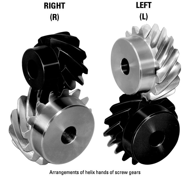
- Right-Handed and Left-Handed Worm Gears: Screw gears can be classified as right-handed or left-handed based on the direction of the helical thread. In a right-handed worm gear, the helical thread advances in a clockwise direction when viewed from the end of the worm. In a left-handed worm gear, the helical thread advances counterclockwise. The choice between right-handed and left-handed worm gears depends on the specific application and the desired rotational direction.
- Non-Throated and Throated Worm Gears: Non-throated worm gears have a cylindrical worm without a groove, while throated worm gears have a groove or a notch on the worm. The presence of a throat allows for greater contact between the worm and the worm wheel, increasing the gear meshing efficiency and load-carrying capacity. Throated worm gears are commonly used in applications where higher efficiency and load capacity are required.
- Self-Locking Worm Gears: Self-locking worm gears are designed to have a high self-locking capability. The helical thread angle and the friction between the worm and the worm wheel prevent the worm wheel from backdriving the worm when the system is at rest. Self-locking worm gears are widely used in applications that require holding a position without the need for additional braking or locking mechanisms, such as elevators, lifts, and positioning systems.
These are some of the different types of screw gears available in the market. The selection of a specific type depends on factors such as torque requirements, gear reduction ratio, precision positioning, load capacity, and self-locking capabilities, among others. Understanding the characteristics and variations of screw gears allows for choosing the most suitable type for a given application.


editor by CX 2023-11-29